V2 DROPPER POST INSTALLATION INSTRUCTIONS
Tools You Will Need
- Cable/Housing Cutters
- Shock pump (For V2 Droppers Only)
- Torque wrench with 3,4,5mm hex bits
- 2mm and 4mm Hex (Shimano I-spec II only)
- 5mm Hex
- T25 torx wrench (Matchmaker X only)
- Clean cloth
- Fibre Grip or Waterproof grease
Assembly time, approximately 20 minutes. Difficulty: medium (depending on frame routing)
COMPLETE EXPLODED VIEW & PARTS LIST

Torque Specs:
- Seat collar to a maximum of 4Nm
- Cable clamping screw, 3mm hex to 3Nm
- Remote body to clamp 3mm hex to 3Nm
- 22.2 Handle bar clamp (if needed) 3mm hex snug to 1Nm max
- Matchmaker X bolt (if needed) 3mm hex to 3Nm
- Seat rail clamp bolts 8Nm
Pressure Spec: Return air spring pressure setting 250-300 PSI at full extension. (Valve access under rubber cover or valve cap (5) below seat clamp assembly)
Note: 27.2 droppers are a sealed cartridge and do not require inflation or pressure adjustment.
STEP 1: ROUTE HOUSING & CABLE
Route the new cable housing and into your frame. Avoid tight bends in your housing routing for smoothest remote action. Please keep in mind this process will range in difficulty depending on the frame. Care & patience will go a long way.
V2.1 Actuator Only: Install the supplied cable barrel onto the cable.

Route the new cable into the housing, starting at the seatpost. The barrel end of the cable should be at the seatpost side of the housing.
STEP 2: PREPARE SEAT TUBE
Now is the best time to prepare your seat tube. Wipe away any debris or grit from top and inside of the seat tube. Apply a fresh layer of either FibreGrip or a waterproof Grease. Both are acceptable.

STEP 3A: (V2.0 Actuator Only) CABLE INTO ACTUATOR
Slide the Actuator O-ring over the Barrel of the cable, push the Barrel into the Actuator window then slide the O-ring back over the cable and Actuator. Snug the housing into its seat at the bottom of the actuator by pulling the remote end of the cable
STEP 3B: (V2.1 Actuator Only)
Open the actuator by hand and place the cable barrel into the actuator cradle. Snug the housing into its seat in the bottom of the actuator by pulling the remote end of the cable.

STEP 4: INSTALL DROPPER
Install the dropper post to your ideal height in the frame and lightly secure the seat clamp. This is best done with two hands, One hand slowly pushes the dropper into the frame and the other hand lightly guides the remote end of the housing out the frame to avoid the housing bunching & kinking. Avoid pulling on the housing during this process.
STEP 5: INSTALL REMOTE
Install the Remote, without cable or housing attached on to your handlebar. (REMOTE INSTALL)
Screw the Barrel Adjuster fully into the Remote body, then loosen 2 full turns.
STEP 6: MEASURE & CUT HOUSING TO LENGTH
Mark the housing at the correct length to reach the barrel adjuster, making sure you have enough slack for full handlebar movement. DO NOT cut the housing yet.
Loosen the seat collar and slide the post/housing out of the frame.
Note: Use the same two hand technique from STEP 4 in reverse.
Slide the post and cable 150mm away from the the housing so that when you cut the housing you don't cut the required cable.
Cut the housing. Make sure the cut end of the housing is not squashed after cutting so the cable slides freely. Install the housing ferrule
Slide the housing back snug against the actuator. You should now have the correct housing length & enough cable to connect the remote.
Slide post back into frame once again using the technique from STEP 4. Lightly snug Seat collar.
STEP 6: CABLE INTO REMOTE
Route your cable into the barrel adjuster on your remote. Feed the cable under the cable clamp bolt and washer on the underside of the lever. Pull the cable tight and clamp the cable 3mm Hex to 3Nm.

STEP 6: ADJUST CABLE TENSION
Remove any lever slack using the Barrel Adjuster. Cut off any excess cable and install the provided cable end.

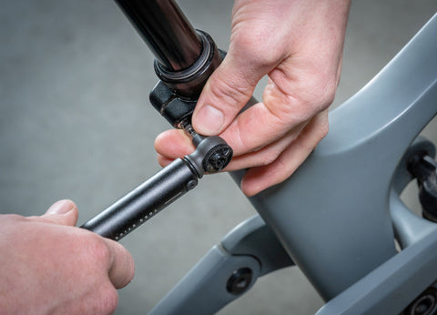
STEP 7: CHECK PRESSURE
If you havent done so already. Now is the time to check the PSI in your post. Attach Shock pump to valve. Inflate post to 250-300psi in the fully extended position. Remove shock pump and reinstall the valve cap on the valve stem

STEP 8: INSTALL SADDLE
Place lower clamp (3) into the cradle of the upper tube (7). Make sure the arrow is pointing forward. Place your saddle on the lower clamp. Holding your saddle, slide the upper clamp (2), arrow forward, under the front clamp nut (1) and place it on top of the saddle rails. You can then drop the rear clamp nut into its seat at the back of the upper clamp. Thread rear clamp bolt (4) into nut and tighten to 8Nm using your 5mm Hex key.

STEP 9: TEST & ADJUST RIDE HEIGHT
Adjust the dropper in the frame to your prefered ride height. Using your torque wench tighten the seat collar to 4Nm. Ride bike around test both function and height of the dropper. Adjust as necessary.
Congratulations, you have now successfully completed the V2 Dropper Installation.
NOW GO RIDE!
If you are having any problems please first double check that you have correctly completed each of the above steps.
If you are still having trouble please email us at support@oneupcomponents.com for help. Please include a detailed description of your issue. Photos are often helpful.
Thanks,
OneUp